ELECTRICAL SAFETY TESTING REFERENCE GUIDE
Hipot, Insulation Resistance, Gound Bond, Leakage Current, Impulse Winding
Reference Guide Contents
OverviewProduct Safety Tests
- Dielectric Strength - Hipot Test
- Ground Continuity, Polarization, and Ground Bond Tests
- Insulation Resistance Test
- Leakage Current Test
Choosing the Right Test Equipment
Applications
Standards
Glossary of Terms
Need Assistance?
Hipot Test Equipment
- AC Hipot Testers
- AC/DC/IR Hipot Testers
- Multi-Channel Hipot Testers
- AC/DC/IR/GB/LC/Dynamic Function Electrical Safety Analyzer
- AC/DC/IR Hipot with Corona Discharge Detection
- Ultra-High Withstand Voltage Hipot Analyzer
Leakage Current Test Equipment
- AC/DC/IR/GB/LC/Dynamic Function Electrical Safety Analyzer
- Capacitor Leakage Current/IR Meter
- LC/IR/PD Battery Cell Insulation Tester
Ground Bond Test Equipment
LCR Meters
Wound Component Testers
- AC/DC/IR/DCR Hybrid Wound Component EST Scanner
- AC/DC/IR/Impulse(Surge)/DCR Wound Component EST Analyzer
- Impulse Winding Tester
Battery Safety Testers
Chroma Systems Solutions
19772 Pauling
Foothill Ranch, CA 92610
949-600-6400
Request a quote
 Get our Newsletter: Click the link below to register.
Follow Us
![]()
![]()
![]()
![]()
Ground Continuity, Polarization, and Ground Bond Tests
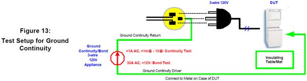
Ground Continuity Test
The purpose of a ground continuity test is to verify that all conductive parts of a product that are exposed to user contact are connected to the power line ground (the "green" wire). The theory is that if an insulation failure occurs that connects power line voltage to an exposed part and a user then comes into contact with that part, current will flow through the low resistance ground path to the green wire, tripping a circuit breaker or blowing a fuse, rather than flowing through the higher resistance of the user's body. Connecting all exposed conductive parts solidly to ground safely diverts the current away from the person.
Since many older homes may be wired as 2-wire systems without solid ground connections, regulatory agencies require all products manufactured with 3-wire cords to pass the same hipot tests as ungrounded products. In such cases, the user is protected by the electrical insulation rather than by the safety ground.
Ground continuity tests are normally performed with a low current DC signal that checks to ensure that the ground connection has a resistance of less than 1 ohm. Ground continuity testing is not only helpful in determining how well a product will fare during a laboratory investigation, but also is useful in a production line environment to ensure quality and user safety.
Polarization Test
A polarization test is usually performed as part of one of the other tests, such as a line voltage leakage or a hipot test. It is a simple test that verifies that a product supplied with a polarized line cord (either a 3-prong plug or a 2-prong plug with the neutral prong larger than the other) is properly connected.
The test may be just a visual inspection or it may be a wiring continuity check. A main purpose of such a test is to ensure that the line and neutral conductors are not interchanged.
Ground Bond Test
The purpose of a ground bond test is to protect the user of a product from hazards that could be caused by an inadequate or faulty ground connection. It differs from a ground continuity test in that it tests how much current the ground circuit can safely carry. Ground bond is a high current AC test that measures resistance of the
ground path under high current conditions.
For example, a product may pass a ground continuity test with a frayed wire containing only a few strands of wire. The circuit, however, would fail immediately if a high current ground fault should occur - causing an open ground connection.
This condition could present a hazard to the user, because part of the product might then have no ground protection at all. If a short occurred between line voltage and an exposed part where no ground exists, users could experience an electrical shock if they touched the part.
The ground bond test, therefore, should verify that the ground circuit has a very low resistance and a high current carrying capacity. This ensures that occurrence of a single ground fault on the product will cause the protective circuit breakers or fuses to shut off power to the device automatically.
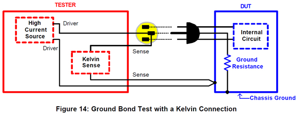
Ground bond testing requires application of a high current source to a conductive surface of the product and measurement of the voltage drop across the ground connection to determine that bonding is adequate and that the circuit can carry the specified current safely. One common method of ground bond testing, shown in Figure 14, applies a 25A source between the protective grounding terminal of the device and all conductive parts that are accessible to the user. The tester used for this purpose supplies the required current and displays the ground circuit resistance in ohms or milliohms.
Because the resistance to ground is usually a very low value, the resistance of the connecting leads from the tester itself can cause errors in the measurement. Such errors can be corrected either by measuring the resistance of the leads before the test and then subtracting that value from the test value or by using a so-called "Kelvin" test setup. A Kelvin connection automatically compensates for the lead resistance by bringing an extra lead to the point of measurement. The extra lead is connected so as to balance out the resistance of the test lead. A typical test setup with a Kelvin connection is illustrated in Figure 14. Most standards recommend a ground resistance of <100 milliohms, excluding the power cable.
Keep reading: Insulation Resistance Test